
提供最適合您的方案
WE PROVIDE YOU THE BEST SOLUTION
運動控制系統及元件
-
 運動控制器+軸卡
-
 步進/伺服驅動器
-
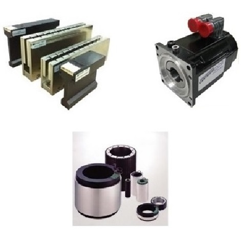 伺服馬達
伺服馬達
步進馬達
音圈馬達
線性馬達
直驅馬達 -
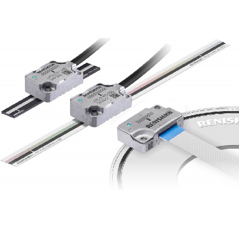 回授元件
回授元件
光學尺
磁性尺
Linear Encoder
編碼器
顯示器 -
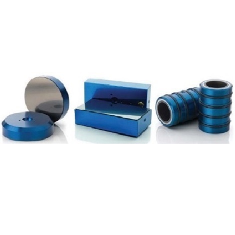 空氣軸承
空氣軸承
Air Bearing
Air conveyor -
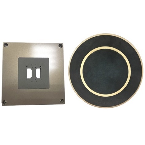 多孔性陶瓷真空吸盤
Porous Ceramic Chuck Table -
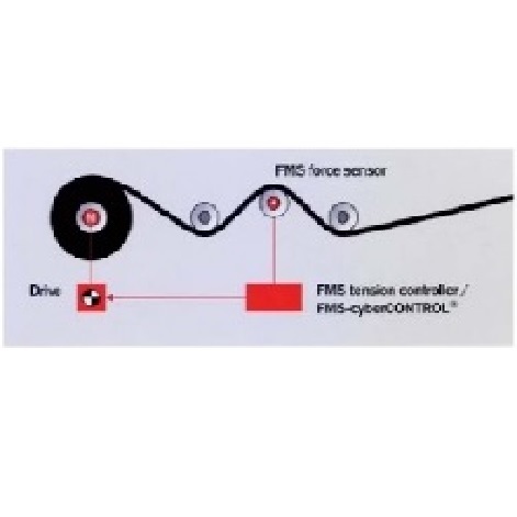 FMS 張力控制器
張力放大器
張力 sensor -
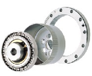 HarmonicDrive® 諧波減速機
DirectDrive Motor 直驅電動機
Rotary Actuator 旋轉執行元件 -
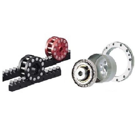 減速機 / 齒輪齒排
-
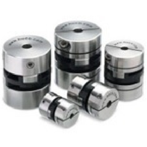 聯軸器 / 免鍵式軸襯
-
 定位平台 (滑台) /
Stage / X-Y-Z Table
Theta Hybrid Hexapod
史都華平台 -
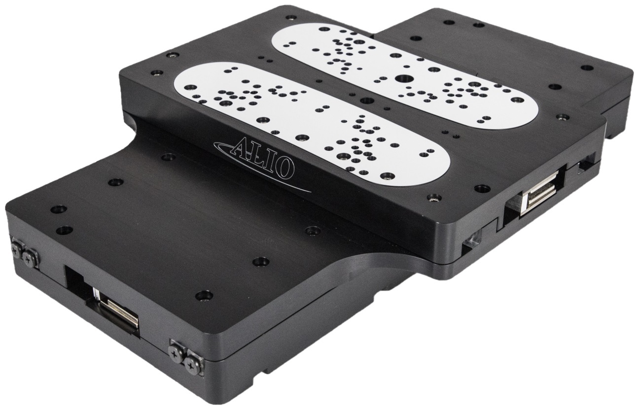
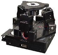 ALIO Hybrid Hexapod
史都華平台 -
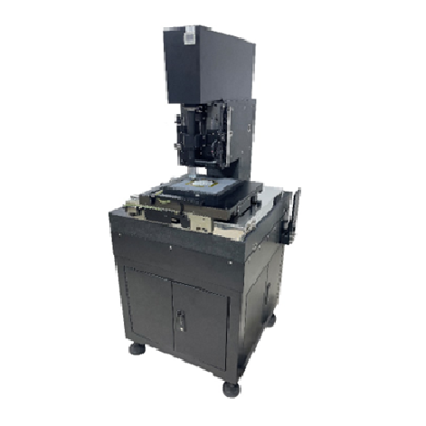 次系統設備(客製)
-
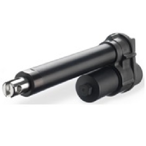 電動缸 / 千斤頂 /
升降器 / 線性致動器 -
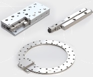 軸承 / 線性軸承 /
線性滑台 -
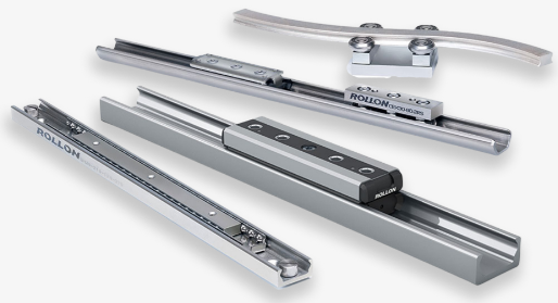 線性滑軌
線性滑軌
-
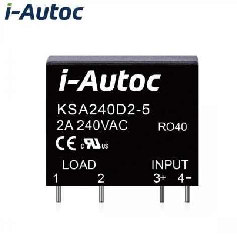 固態繼電器SSR
-
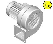 Karl Klein 鼓風機
-
 特殊環境用--
防爆、防水、
真空、低溫、重載 -
 應用案例影片
-
 庫存出清
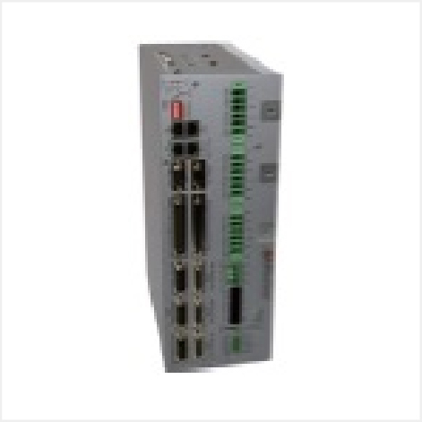
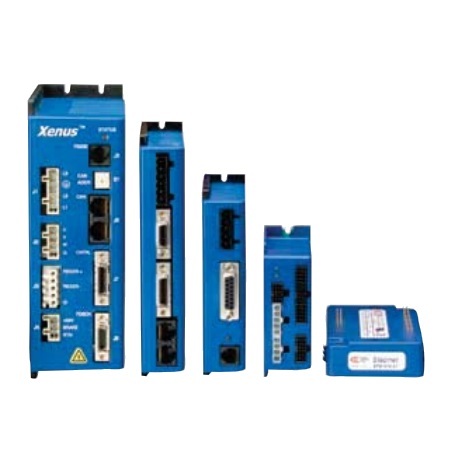
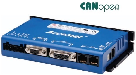
庫存出清
Accelnet 線性伺服驅動器 DC 電源入力 (ADP、ACJ、ACM、ACK、APM、AEM、AP2、AE2、BPL、BP2、BEL、BE2、BML、ACK-HC、R20、R21、R22、R23、R42、R43、AEP、AEV、APV)
|
PDF下載 |
|||||||||||
|
|
|||||||||||
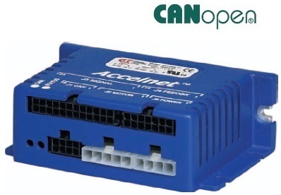
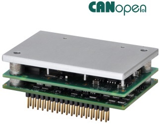
Accelnet Panel

ADP Panel
Control Modes
• Indexer, Point-to-Point, PVT
• Camming, Gearing, Position, Velocity, Torque
Command Interface
• Stepper commands
Single-ended or Differential selectable
• CANopen
• ASCII and discrete I/O
• ±10V position/velocity/torque command
• PWM position/velocity/torque command
• Master encoder (Gearing/Camming)
Communications
• CANopen
• RS232
Feedback
• Digital Quad A/B encoders
• Analog sin/cos encoder (-S option)
• Brushless resolver (-R option)
• Aux encoder / emulated encoder output
• Digital Halls
I/O - Digital
• 12 inputs, 3 outputs
Dimensions: mm [in]
• 168 x 99 x 31 [6.6 x 3.9 x 1.2]
|
Model |
VDC |
IC |
IP |
|
ADP-055-18 |
55 |
6 |
18 |
|
ADP-090-09 |
90 |
3 |
9 |
|
ADP-090-18 |
90 |
6 |
18 |
|
ADP-090-36 |
90 |
12 |
36 |
|
ADP-180-09 |
180 |
3 |
9 |
|
ADP-180-18 |
180 |
6 |
18 |
| ADP-180-30 | 180 | 15 | 30 |
Add -S to part numbers above for sin/cos feedback
Add -R to part numbers above for resolver feedback
DESCRIPTION
Accelnet is a high-performance, DC powered drive for position,
velocity (using encoder, resolver, Halls, or BEMF), and torque control
of brushless and brush motors. It can operate as a distributed drive
using the CANopen, or as a stand-alone drive accepting analog or
digital commands from an external motion controller. In stand-alone
mode, current and velocity modes accept digital 50% PWM or PWM/
polarity inputs as well as ±10V analog. In position mode inputs can
be incremental position commands from step-motor controllers,
analog ±10V, or A/B quadrature commands from a master-encoder.
Pulse to position ratio is programmable for electronic gearing.
Drive commissioning is fast and simple using CME 2™ software
operating under Windows® and communicating with Accelnet via
CAN or an RS-232 link. CAN address selection is by a 16-position
rotary switch. If there are more than sixteen devices on the CAN bus,
the additional address bits needed can come from programmable
inputs, or can be set in flash memory.
Accelnet models operate as Motion Control Devices under the
DSP-402 protocol of the CANopen DS-301 V4.01 (EN 50325-4)
application layer.
DSP-402 modes supported include: Profile Position, Profile Velocity,
Profile Torque, Interpolated Position Mode (PVT),and Homing. The
two CAN ports are optically isolated from drive circuits.
Digital quad A/B encoders and Halls are standard feedback devices.
Sin/cos analog encoders are supported in models with an “S”
appended to the part number. Resolver feedback is supported in
models with“R” appended to the part number.
There are twelve digital inputs eleven of which have programmable
functions. These include CAN address, motion-abort, limit & home
switches, stepper/encoder pulse inputs, reset, digital torque or
velocity reference, and motor over-temperature. Input [IN1] is
dedicated for the drive Enable. There are three programmable
logic outputs for reporting an drive fault, motor brake control, or
other status indications.
Drive power is transformer-isolated DC from regulated or
unregulated power supplies. An AuxHV input powers control circuits
for “keep-alive” operation permitting the drive power stage to be
completely powered down without losing position information, or
communications with the control system.

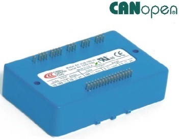
ACJ Micro Panel
Feedback Versions
• Analog Sin/Cos
• Quad A/B digital
Control Modes
• Indexer, Point-to-Point, PVT
• Camming, Gearing, Position, Velocity, Torque
Command Interface
• CANopen
• ASCII and discrete I/O
• Stepper commands
• ±10V position/velocity/torque command
• PWM position*/velocity/torque command
• Master encoder (Gearing/Camming)
Communications
• CANopen
• RS-232
Feedback
• Digital Quad A/B encoder
• Secondary encoder / emulated encoder out
• Brushless resolver (-R versions)
• Analog sin/cos encoder (-S versions)
• Digital Halls
I/O - Digital
• 9 inputs, 4 outputs
Dimensions: mm [in]
• 97 x 64 x 33 [3.8 x 2.5 x 1.3]
* ACJ-R models
| model
|
VDC |
IC |
IP |
|
ACJ-055-09 |
20-55 |
3 |
9 |
|
ACJ-055-18 |
20-55 |
6 |
18 |
|
ACJ-090-03 |
20-90 |
1 |
3 |
|
ACJ-090-09 |
20-90 |
3 |
9 |
|
ACJ-090-12 |
20-90 |
6 |
12 |
DESCRIPTION
Accelnet Micro Panel is a compact, DC powered servo drive
for position, velocity, and torque control of AC brushless and
DC brush motors. It can operate on a distributed control
network, as a stand-alone indexing drive, or with external
motion controllers. Standard feedback is digital quad A/B
encoder and two option versions are available to support
brushless resolver (-R), or analog sin/cos encoders (-S).
Indexing mode enables simplified operation with PLC’s which
use outputs to select and launch indexes and inputs to
read back drive status. Additionally, a PLC can send ASCII
data that can change motion profiles so that one index can
perform various motions as machine requirements change.
The CANopen distributed control architecture is also
supported. As a CAN node operating under the CANopen
protocol, it supports Profile Position, Profile Velocity, Profile
Torque, Interpolated Position, and Homing. Up to 127 drives
can operate on a single CAN bus and groups of drives can
be linked via the CAN so that they execute motion profiles
together.
Operation with external motion controllers is possible
in torque (current), velocity, and position modes. Input
command signals can be ±10V (torque, velocity, position),
PWM/Polarity (torque, velocity), or stepper format (CU/CD
or Step/Direction).

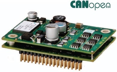
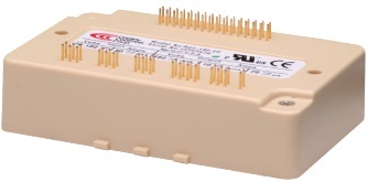
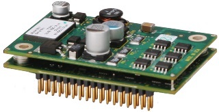
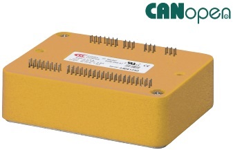
ACM Accelnet Module
CONTROL MODES
• Indexer, Point-to-Point, PVT
• Camming, Gearing, Position, Velocity, Torque
COMMAND INTERFACE
• CANopen
•ASCII and discrete I/O
• Stepper commands
•±10 Vdc analog position/velocity/torque *
• PWM velocity/torque command
• Master encoder (Gearing/Camming)
COMMUNICATIONS
• CANopen
• RS-232
FEEDBACK
• Digital Quad A/B encoder
• Secondary encoder
• Brushless resolver (-R option)
• Digital Halls
I/O - DIGITAL
• 10 inputs, 2 outputs
DIMENSIONS: MM [IN]
• 102 x 69 x 25 [4.0 x 2.7 x 1.0]
* Available on RoHS versions
|
Model |
VDC |
IC |
IP |
|
ACM-055-18 |
20-55 |
6 |
18 |
|
ACM-090-09 |
20-90 |
3 |
9 |
|
ACM-090-24 |
20-90 |
12 |
24 |
| ACM-090-60 | 20-90 | 30 | 60 |
|
ACM-180-09 |
20-180 |
3 |
9 |
|
ACM-180-18 |
20-180 |
6 |
18 |
|
ACM-180-20 |
20-180 |
10 |
20 |
Add -R to part numbers above for resolver feedback
DESCRIPTION
Accelnet is a digital servo drive that combines CANopen networking
with 100% digital control of brush or brushless motors in a pc board
mounting package with power options to 10 Adc continuous and
20 Adc peak from 20 Vdc to 180 Vdc power supplies.
RoHS compliance is now standard on all models and with this a
±10 Vdc analog input has been added for position/velocity/torque
control. The input takes the place of signal ground pins on non
RoHS models so that RoHS types can be installed in place of non
RoHS types with no change in function.
Accelnet operates as a Motion Control Device using the DSP-
402 protocol under the CANopen DS-301 V4.01 (EN 50325-4)
application layer. DSP-402 modes supported include Interpolated
Position (PVT), Profile Position, Profile Velocity, Profile Torque,
and Homing.
Ten logic inputs are configurable as CAN address bits, enables,
limit & home switches, motor temperature switch, stepper/encoder
pulses, and reset. There are two logic outputs for reporting drive
status, or driving a motor brake.
In addition to CANopen motion commands, Accelnet can operate
using incremental position commands from step-motor controllers
in Pls/Dir or CW/CCW format, as well as A/B quadrature commands
from a master-encoder which can drive cam tables or be geared to
ratio the drive position to that of the master-encoder.
Drive commissioning is facilitated by CME 2™ software operating
under Windows® communicating with Accelnet via an RS-232
link. Auto-tuning algorithms in CME 2™ slash set up times for fast
system commissioning by automating motor phasing, and currentloop
tuning. A powerful oscilloscope and waveform generator display
drive performance for fine tuning. Drive configurations are saved
in non-volatile flash memory. OEM’s can inventory one part, and
configure drives on-site to each axis in a machine.
Space-vector modulation delivers higher motor speeds and lower
motor power dissipation than conventional sine-pwm modulation.
Carrier-cancellation modulation all but eliminates motor ripple
current and dissipation at a standstill. Current-loop sampling is at 15
kHz, position and velocity loops at 3 kHz and PWM ripple at 30 kHz.
All drive circuits are DC coupled and operate from unregulated
transformer-isolated linear DC power supplies, or regulated
switching power supplies.
The PC board mounting package is suitable for high density, multiaxis
installations in equipment where space is at a premium, and
wiring must be minimized.

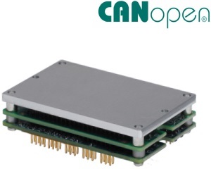
ACK Micro Module
Control Modes
• Indexer, Point-to-Point, PVT
• Camming, Gearing, Position, Velocity, Torque
Command Interface
• CANopen/DeviceNet
• ASCII and discrete I/O
• Stepper commands
• ±10V position/velocity/torque command
• PWM velocity/torque command
• Master encoder (Gearing/Camming)
Communications
• CANopen/DeviceNet
• RS232
Feedback
• Digital Quad A/B encoder
• Secondary encoder
• Digital Halls
• Resolver (-R option)
I/O - Digital
• 10 inputs, 3 outputs
Dimensions: mm [in]
• 64 x 41 x 21 [2.5 x 1.6 x 0.83]
|
Model |
VDC |
IC |
IP |
|
ACK-055-06 |
14-55 |
3 |
6 |
|
ACK-055-10 |
20-55 |
5 |
10 |
|
ACK-090-04 |
14-90 |
2 |
4 |
| ACK-090-08 | 20-90 | 4 | 8 |
| ACK-090-20 | 14-90 | 10 | 20 |
|
ACK-090-30 |
14-90 |
15 |
30 |
FOR RESOLVER OPTION, ADD “-R” TO THE PART NUMBER
DESCRIPTION
Accelnet Micro Module is a digital servodrive that combines CANopen
networking with 100% digital control of brush or brushless motors
in a PC board mounting package with power options to 5 Adc
continuous and 10 Adc peak from 14 to 90 Vdc power supplies.
Accelnet Micro Module operates as a Motion Control Device using
the DSP-402 protocol under the CANopen DS-301 V4.01 (EN
50325-4) application layer. DSP-402 modes supported include
Interpolated Position (PVT), Profile Position, Profile Velocity, Profile
Torque, and Homing.
There are ten logic inputs. One is dedicated to the Amp Enable
function, the other nine are programmable. There are three logic
outputs rated to +30 Vdc.
Used as a stand-alone drive, Accelnet Micro Module can operate
using incremental position commands from step-motor controllers
in Pulse/Direction or CU/CD format, as well as A/B quadrature
commands from a master-encoder.Torque or velocity control can
be from digital PWM signals, or analog ±10 V.
Drive commissioning is facilitated by CME 2™ software operating
under Windows® communicating with Accelnet Micro Module via
CAN or an RS-232 link.
Auto-tuning algorithms in CME 2™ slash set up times for fast
system commissioning by automating motor phasing, and currentloop
tuning.
A powerful oscilloscope and waveform generator displays drive
performance for fine tuning. Drive configurations are saved in nonvolatile
flash memory. OEM’s can inventory one part, and configure
drives on-site to each axis in a machine.
Space-vector modulation delivers higher motor speeds and lower
motor power dissipation than conventional sine-PWM modulation.
Carrier-cancellation modulation all but eliminates motor ripple
current and dissipation at a standstill. Current-loop sampling is at 15
kHz, position and velocity loops at 3 kHz and PWM ripple at 30 kHz.
All drive circuits are DC coupled and operate from unregulated
transformer-isolated linear DC power supplies, or regulated
switching power supplies.
The PC-board mounting package is suitable for high-density, multiaxis
installations in equipment where space is at a premium, and
wiring must be minimized.

APM AccelnetPLUS Module
Control Modes
• Profile Position-Velocity-Torque, Interpolated Position, Homing
• Camming, Gearing
• Indexer
Command Interface
• CANopen
• ASCII and discrete I/O
• Stepper commands
• ±10V position/velocity/torque command
• PWM velocity/torque command
• Master encoder (Gearing/Camming)
Communications
• CANopen
• RS-232
Feedback
• Digital quad A/B encoder
Analog sin/cos incremental
Panasonic Incremental A Format
• SSI, EnDat, Absolute A
Tamagawa & Panasonic Absolute A
Sanyo Denki Absolute A,
BiSS,BiSS
• Aux. encoder / encoder out
• Digital Halls
I/O
• Digital: 11 inputs, 6 outputs
• Analog: 1, 12-bit input
Dimensions: mm [in]
• 76.3 x 58.2 x 20.5 [3.01 x 2.29 x 0.81]
|
Model |
VDC |
IC |
IP |
|
APM-090-06 |
14-90 |
3 |
6 |
|
APM-090-14 |
14-90 |
7 |
14 |
|
APM-090-30 |
14-90 |
15 |
30 |

DESCRIPTION
Accelnet APM is a high-performance, DC powered servo drive
for position, velocity, and torque control of brushless and brush
motors via CANopen. Using advanced FPGA technology, the APM
provides a significant reduction in the cost per node in multi-axis
CANopen systems.
The APM operates as an CANopen node using the CANopen over
CANopen (CoE) protocol of DSP-402 for motion control devices.
Supported modes include: Profile Position-Velocity-Torque,
Interpolated Position Mode (PVT), and Homing.
Command sources also include ±10V analog torque/velocity/
position, PWM torque/velocity, and stepper command pulses.
Feedback from a number of incremental and absolute encoders is
supported.
Nine high-speed digital inputs with programmable functions are
provided, and a low-speed input for motor temperature switches.
An SLI (Switch & LED Interface) function is supported by another
high-speed input and four high-speed digital outputs. If not used for
SLI, the input and outputs are programmable for other functions.
Two open-drain MOSFET outputs can drive loads powered up to
24 Vdc.
An RS-232 serial port provides a connection to Copley’s CME2
software for commissioning, firmware upgrading, and saving
configurations to flash memory.
Drive power is transformer-isolated DC from regulated or
unregulated power supplies. An AuxHV input is provided for
“keep-alive” operation permitting the drive power stage to be
completely powered down without losing position information, or
communications with the control system.

AEM
Control Modes
• Cyclic Synchronous Position-Velocity-Torque (CSP, CSV, CST)
• Indexer, Point-to-Point, PVT
• Camming, Gearing
Command Interface
• CAN application layer over EtherCAT (CoE)
• ASCII and discrete I/O
• Stepper commands
• ±10V position/velocity/torque command
• PWM velocity/torque command
• Master encoder (Gearing/Camming)
Communications
• EtherCAT
• RS-232
Feedback
• Digital quad A/B encoder
Analog sin/cos incremental
Panasonic Incremental A Format
• SSI, EnDat, Absolute A
Tamagawa & Panasonic Absolute A
Sanyo Denki Absolute A,
BiSS,BiSS
• Aux. encoder / encoder out
• Digital Halls
I/O
• Digital: 11 inputs, 6 outputs
• Analog: 1, 12-bit input
Dimensions: mm [in]
• 76.3 x 58.2 x 20.5 [3.01 x 2.29 x 0.81]
|
Model |
VDC |
IC |
IP |
|
AEM-090-06 |
14-90 |
3 |
6 |
|
AEM-090-14 |
14-90 |
7 |
14 |
| AEM-090-30 | 14-90 | 15 | 30 |
| AEM-180-14 | 40-180 | 7 | 14 |
|
AEM-180-20 |
40-180 |
10 |
20 |
DESCRIPTION
Accelnet AEM is a high-performance, DC powered servo drive for
position, velocity, and torque control of brushless and brush motors
via EtherCAT, an Ethernet-based fieldbus. Using advanced FPGA
technology, the AEM provides a significant reduction in the cost
per node in multi-axis EtherCAT systems.
The AEM operates as an EtherCAT slave using the CAN application
layer over EtherCAT (CoE) protocol of DSP-402 for motion control
devices. Supported modes include: Cyclic Synchronous Position-
Velocity-Torque, Profile Position-Velocity-Torque, Interpolated
Position Mode (PVT), and Homing.
Command sources also include ±10V analog torque/velocity/
position, PWM velocity/torque, and stepper command pulses.
Feedback from a number of incremental and absolute encoders is
supported.
Nine high-speed digital inputs with programmable functions are
provided, and a low-speed input for motor temperature switches.
An SLI (Switch & LED Interface) function is supported by another
high-speed input and four high-speed digital outputs. If not used for
SLI, the input and outputs are programmable for other functions.
Two open-drain MOSFET outputs can drive loads powered up to
24 Vdc.
An RS-232 serial port provides a connection to Copley’s CME2
software for commissioning, firmware upgrading, and saving
configurations to flash memory.
Drive power is transformer-isolated DC from regulated or
unregulated power supplies. An AuxHV input is provided for
“keep-alive” operation permitting the drive power stage to be
completely powered down without losing position information or
communications with the control system.
AP2
Control Modes
• Profile Position-Velocity-Torque, Interpolated Position, Homing
• Camming, Gearing
• Indexer
Command Interface
• CANopen
• ASCII and discrete I/O
• Stepper commands
• ±10V position/velocity/torque command
• PWM velocity/torque command
• Master encoder (Gearing/Camming)
Communications
• CANopen
• RS-232
Feedback
• Digital quad A/B encoder
Analog sin/cos incremental
Panasonic Incremental A Format
• SSI, EnDat, Absolute A,
Tamagawa & Panasonic Absolute A
Sanyo Denki Absolute A,
BiSS,BiSS
• Aux. encoder / encoder out
• Digital Halls
I/O
• Digital: 20 inputs, 7 outputs
• Analog: 2, 12-bit inputs
Dimensions: mm [in]
• 114 x 73 x 20.6 [4.5 x 2.9 x 0.8]
|
Model |
VDC |
IC |
IP |
|
AP2-090-06 |
14-90 |
3 |
6 |
|
AP2-090-14 |
14-90 |
7 |
14 |
|
AP2-090-30 |
14-90 |
15 |
30 |

DESCRIPTION
Accelnet AP2 is a high-performance, DC powered servo drive for
position, velocity, and torque control of brushless and brush motors.
Using advanced FPGA technology, the AP2 provides a significant
reduction in the cost per node in multi-axis CANopen systems.
Each of the two nodes in the AP2 operates as an CANopen node
using the CANopen protocol DSP-402 for motion control devices.
Supported modes include: Profile Position-Velocity-Torque,
Interpolated Position Mode (PVT), and Homing.
Command sources also include ±10V analog torque/velocity/
position, PWM torque/velocity, and stepper command pulses..
Feedback from a number of incremental and absolute encoders is
supported.
Seventeen high-speed digital inputs with programmable functions
are provided, and two low-speed inputs for motor temperature
switches.
An SLI (Switch & LED Interface) function is supported by another
high-speed input and four high-speed digital outputs. If not used for
SLI, the input and outputs are programmable for other functions.
Three open-drain MOSFET can drive loads powered up to 24 Vdc.
An RS-232 serial port provides a connection to Copley’s CME2
software for commissioning, firmware upgrading, and saving
configurations to flash memory.
Drive power is transformer-isolated DC from regulated or
unregulated power supplies. An AuxHV input is provided for
“keep-alive” operation permitting the drive power stage to be
completely powered down without losing position information, or
communications with the control system.
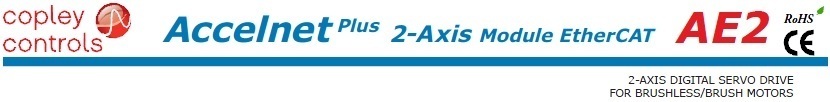
AE2
Control Modes
• Cyclic Synchronous Position-Velocity-Torque (CSP, CSV, CST)
• Profile Position-Velocity-Torque, Interpolated Position, Homing
• Camming, Gearing
• Indexer
Command Interface
• CAN application layer over EtherCAT (CoE)
• ASCII and discrete I/O
• Stepper commands
• ±10V position/velocity/torque command
• PWM velocity/torque command
• Master encoder (Gearing/Camming)
Communications
• EtherCAT
• RS-232
Feedback
• Digital quad A/B encoder
Analog sin/cos incremental
Panasonic Incremental A Format
• SSI, EnDat, Absolute A,
Tamagawa & Panasonic Absolute A
Sanyo Denki Absolute A,
BiSS,BiSS
• Aux. encoder
• Digital Halls
I/O
• Digital: 20 inputs, 7 outputs
• Analog: 2, 12-bit inputs
Dimensions: mm [in]
• 114 x 73 x 20.6 [4.5 x 2.9 x 0.8]
|
Model |
VDC |
IC |
IP |
|
AE2-090-06 |
14-90 |
3 |
6 |
|
AE2-090-14 |
14-90 |
7 |
14 |
|
AE2-090-30 |
14-90 |
15 |
30 |

DESCRIPTION
Accelnet AE2 is a dual-axis, high-performance, DC powered servo
drive for position, velocity, and torque control of brushless and brush
motors via EtherCAT, an Ethernet-based fieldbus. Using advanced
FPGA technology, the AE2 provides a significant reduction in the
cost per axis in multi-axis EtherCAT systems.
Each of the two axes in the AE2 operates as an EtherCAT slave using
the CAN application layer over EtherCAT (CoE) protocol of DSP-
402 for motion control devices. Supported modes include: Cyclic
Synchronous Position-Velocity-Torque, Profile Position-Velocity-
Torque, Interpolated Position Mode (PVT), and Homing.
Command sources also include ±10V analog torque/velocity/
position, PWM velocity/torque, and stepper command pulses.
Feedback from a number of incremental and absolute encoders is
supported.
Seventeen high-speed digital inputs with programmable functions
are provided, and two low-speed inputs for motor temperature
switches.
An SLI (Switch & LED Interface) function is supported by combining
a high-speed input with four high-speed digital outputs. If not used
for SLI, the input and outputs are programmable for other functions.
Three open-drain MOSFET outputs can drive loads powered up to
24 Vdc.
An RS-232 serial port provides a connection to Copley’s CME2
software for commissioning, firmware upgrading, and saving
configurations to flash memory.
Drive power is transformer-isolated DC from regulated or
unregulated power supplies. An AuxHV input is provided for
“keep-alive” operation permitting the drive power stage to be
completely powered down without losing position information, or
communications with the control system.
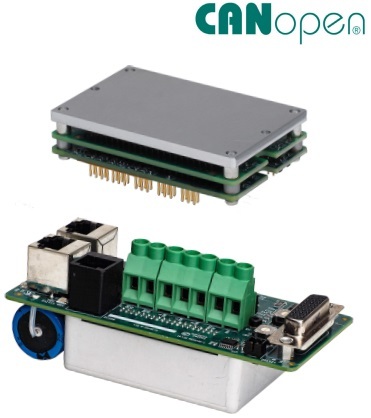
Accelnet Plus Panel CANopen BPL
CONTROL MODES
• Profile Position-Velocity-Torque, Interpolated Position, Homing
• Camming, Gearing
• Indexer
COMMAND INTERFACE
• CANopen
• ASCII and discrete I/O
• Stepper commands
• ±10V position/velocity/torque
• PWM velocity/torque command
• Master encoder (Gearing/Camming)
COMMUNICATIONS
• CANopen
• RS-232
FEEDBACK Incremental Encoders
• Digital quad A/B
Analog Sin/Cos
Panasonic Incremental A Format
• Aux. quad A/B encoder / encoder out Absolute Encoders
• SSI, EnDat, Absolute A,
Tamagawa & Panasonic Absolute A
Sanyo Denki Absolute A, BiSS (B & C)
Resolver (-R option)
• Brushless Resolver
Other
• Digital Halls
I/O DIGITAL
• 6 High-speed inputs
• 1 Motor over-temp input
• 4 Opto-Isolated inputs
• 3 Opto-Isolated outputs
• 1 Opto-Isolated brake output
I/O ANALOG
• 1 Reference Input, 12-bit
SAFE TORQUE OFF (STO)
• SIL 3, Category 3, PL d
DIMENSIONS: IN [MM]
• 5.08 x 3.41 x 1.99 [129 x 86.6 x 50.4]
• 5.08 x 3.41 x 3.39 [129 x 86.6 x 86.1] with heatsink
|
Model |
VDC |
IC |
IP |
|
BPL-090-06 |
90 |
3 |
6 |
|
BPL-090-14 |
90 |
7 |
14 |
|
BPL-090-30 |
90 |
15 |
30 |
Add -R for resolver feedback option
DESCRIPTION
The BPL is a high-performance, DC powered drive for position, velocity,
and torque control of brushless and brush motors via CANopen.
Drive commissioning is fast and simple using CME 2™ software operating under Windows®
and communicating with the BPL via RS-232.
The BPL operates as a CANopen DS-402 node.
Supported modes include: Profile Position-Velocity-Torque,
Interpolated Position Mode (PVT), and Homing.
Feedback from both incremental and absolute encoders is supported.
A multi-mode encoder port functions as an input or output depending on the drive’s basic setup.
There are seven non-isolated inputs. All inputs have programmable active levels.
Three opto-isolated outputs [OUT1~3] have individual +/- connections.
An isolated MOSFET brake output [OUT4] is programmable to drive motor brakes or other functions
and has a flyback diode to the Brake 24V input for driving inductive loads.
Drive power is transformer-isolated DC from regulated or unregulated power supplies.
An AuxHV input is provided for “keep-alive” operation permitting the drive power stage
to be completely powered down without losing position information, or communications with the control system.
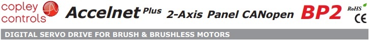
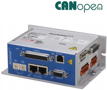
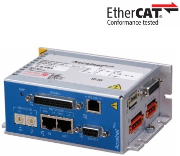
Accelnet Plus 2-Axis Panel CANopen BP2
CONTROL MODES
• Profile Position-Velocity-Torque, Interpolated Position, Homing
• Camming, Gearing
• Indexer
COMMAND INTERFACE
• CANopen
• ASCII and discrete I/O
• Stepper commands
• ±10V position/velocity/torque
• PWM velocity/torque command
• Master encoder (Gearing/Camming)
COMMUNICATIONS
• CANopen DS-402
• RS-232
FEEDBACK Incremental Encoders
• Digital quad A/B
Analog Sin/Cos
Panasonic Incremental A Format
• Aux. quad A/B encoder / encoder out
Absolute Encoders
• SSI, EnDat, Absolute A,
Tamagawa & Panasonic Absolute A
Sanyo Denki Absolute A, BiSS (B & C)
Other
• Digital Halls
I/O DIGITAL
• 8 High-speed inputs
• 2 Motor over-temp inputs
• 8 Opto-Isolated inputs
• 5 Opto-Isolated outputs
• 2 Opto-Isolated brake outputs
ANALOG
• 2 Reference Inputs, 12-bit
SAFE TORQUE OFF (STO)
• SIL 3, Category 3, PL d
DIMENSIONS: IN [MM]
• 6.78 x 4.70 x 1.74 [172.1 x 119.3 x 44.1] no heatsink
• 6.78 x 4.70 x 3.14 [172.1 x 119.3 x 79.8] with heatsink
|
Model |
VDC |
IC |
IP |
|
BP2-090-06 |
90 |
3 |
6 |
|
BP2-090-14 |
90 |
7 |
14 |
|
BP2-090-20 |
90 |
10 |
20 |
Current ratings are for each axis
Add -R for resolver feedback option
DESCRIPTION
The BP2 is a high-performance, DC powered drive for position, velocity,
and torque control of brushless and brush motors via CANopen.
Drive commissioning is fast and simple using CME 2™ software operating under Windows®
and communicating with the BP2 via RS-232.
The BP2 operates as a CANopen DS-402 node.
Supported modes include: Profile Position-Velocity-Torque, Interpolated Position Mode (PVT), and Homing.
Feedback from both incremental and absolute encoders is supported.
A multi-mode encoder port functions as an input or output depending on the drive’s basic setup.
As an input it takes feedback from a secondary encoder to create a dual-loop position control system
or as a master encoder for driving a cam table.
As an output, it buffers the digital encoder signals from the motor’s digital encoder
and eliminates split cables that would be needed to send the signals to both drive and control system.
There are ten non-isolated inputs. Eight opto-isolated digital inputs are bipolar types that source or
sink current into a common connection that can be tied to ground or +24V.
[IN1&10] default to the drive Enable function for axes A & B, and are programmable to other functions.
The other inputs are programmable. All inputs have programmable active levels.
Five opto-isolated outputs [OUT1~5] have individual collector/emitter connections.
Two MOSFET outputs [OUT6~7] are programmable to drive motor brakes or other functions.
Drive power is transformer-isolated DC from regulated or unregulated power supplies.
An AuxHV input is provided for “keep-alive” operation permitting the drive power stage to
be completely powered down without losing position information, or communications with the control system.
資料來源: https://www.copleycontrols.com/wp-content/uploads/2018/02/BP2-ds.pdf

Accelnet Plus Panel EtherCAT BEL
CONTROL MODES
• Cyclic Synchronous Position-Velocity-Torque (CSP, CSV, CST)
• Profile Position-Velocity-Torque, Interpolated Position, Homing
• Camming, Gearing
• Indexer
COMMAND INTERFACE
• CAN application protocol over EtherCAT (CoE)
• ASCII and discrete I/O
• Stepper commands
• ±10V position/velocity/torque
• PWM velocity/torque command
• Master encoder (Gearing/Camming)
COMMUNICATIONS
• EtherCAT
• RS-232
FEEDBACK Incremental Encoders
• Digital quad A/B
Analog Sin/Cos
Panasonic Incremental A Format
• Aux. quad A/B encoder / encoder out
Absolute Encoders
• SSI, EnDat, Absolute A,
Tamagawa & Panasonic Absolute A
Sanyo Denki Absolute A, BiSS (B & C)
Resolver (-R option)
• Brushless Resolver Other
• Digital Halls
I/O DIGITAL
• 6 High-speed inputs
• 1 Motor over-temp input
• 4 Opto-Isolated inputs
• 3 Opto-Isolated outputs
• 1 Opto-Isolated brake output
I/O ANALOG
• 1 Reference Input, 12-bit
SAFE TORQUE OFF (STO)
• SIL 3, Category 3, PL d
DIMENSIONS: IN [MM]
• 5.08 x 3.41 x 1.99 [129 x 86.6 x 50.4]
• 5.08 x 3.41 x 3.39 [129 x 86.6 x 86.1] with heatsink
|
Model |
VDC |
IC |
IP |
|
BEL-090-06 |
90 |
3 |
6 |
|
BEL-090-14 |
90 |
7 |
14 |
|
BEL-090-30 |
90 |
15 |
30 |
Add -R for resolver feedback option
DESCRIPTION
The BEL is a high-performance, DC powered drive for position, velocity,
and torque control of brushless and brush motors via EtherCAT, an Ethernet-based fieldbus.
The BEL operates as an EtherCAT slave using the CANopen application protocol over EtherCAT (CoE).
Supported modes include: Profile Position-VelocityTorque, Cyclic Synchronous Position-Velocity-Torque,
Interpolated Position Mode (PVT), Homing, and CSTCA (Cyclic-sync torque with commutation angle).
Feedback from both incremental and absolute encoders is supported.
A multi-mode encoder port functions as an input or output depending on the drive’s basic setup.
There are seven non-isolated inputs. All inputs have programmable active levels.
Three opto-isolated outputs [OUT1~3] have individual +/- connections.
An isolated MOSFET brake output [OUT4] is programmable to drive motor brakes or other functions
and has a flyback diode to the Brake 24V input for driving inductive loads.
Drive power is transformer-isolated DC from regulated or unregulated power supplies.
An AuxHV input is provided for “keep-alive” operation permitting the drive power stage
to be completely powered down without losing position information,
or communications with the control system.
資料來源: https://www.copleycontrols.com/wp-content/uploads/2018/02/BEL-ds.pdf
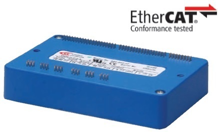
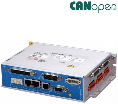
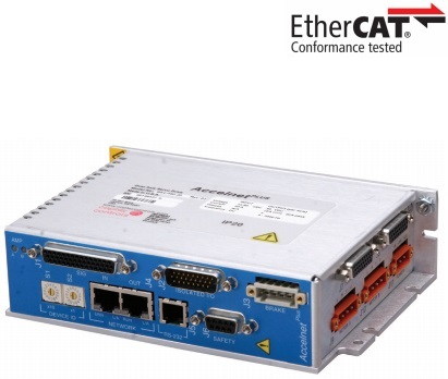
Accelnet Plus 2-Axis Panel EtherCAT BE2
CONTROL MODES
• Cyclic Synchronous Position-Velocity-Torque (CSP, CSV, CST)
• Profile Position-Velocity-Torque, Interpolated Position, Homing
• Camming, Gearing
• Indexer
COMMAND INTERFACE
• CANopen application protocol over EtherCAT (CoE)
• ASCII and discrete I/O
• Stepper commands
• ±10V position/velocity/torque
• PWM velocity/torque command
• Master encoder (Gearing/Camming)
COMMUNICATIONS
• EtherCAT
• RS-232
FEEDBACK Incremental Encoders
• Digital quad A/B
Analog Sin/Cos
Panasonic Incremental A Format
• Aux. quad A/B encoder / encoder out
Absolute Encoders
• SSI, EnDat, Absolute A,
Tamagawa & Panasonic Absolute A
Sanyo Denki Absolute A, BiSS (B & C)
Other
• Digital Halls
I/O DIGITAL
• 8 High-speed inputs
• 2 Motor over-temp inputs
• 8 Opto-Isolated inputs
• 5 Opto-Isolated outputs
• 2 Opto-Isolated brake outputs
ANALOG
• 2 Reference Inputs, 12-bit
SAFE TORQUE OFF (STO)
• SIL 3, Category 3, PL d
DIMENSIONS: IN [MM]
• 6.78 x 4.70 x 1.74 [172.1 x 119.3 x 44.1] no heatsink
• 6.78 x 4.70 x 3.14 [172.1 x 119.3 x 79.8] with heatsink
|
Model |
VDC |
IC |
IP |
|
BE2-090-06 |
90 |
3 |
6 |
|
BE2-090-14 |
90 |
7 |
14 |
|
BE2-090-20 |
90 |
10 |
20 |
Current ratings are for each axis
Add -R for resolver feedback option
DESCRIPTION
The BEL models are high-performance, DC powered drives for position, velocity,
and torque control of brushless and brush motors via EtherCAT, an Ethernet-based fieldbus.
These drives operate as EtherCAT slaves using the CANopen application protocol over
EtherCAT (CoE) protocol of DSP-402 for motion control devices.
Supported modes include: Cyclic Synchronous Position-VelocityTorque, Profile Position-Velocity-Torque,
Interpolated Position Mode (PVT), and Homing. Feedback from both incremental and absolute encoders is supported.
A multi-mode encoder port functions as an input or output depending on the drive’s basic setup.
There are ten non-isolated inputs and eight isolated inputs. All inputs have programmable active levels.
Five opto-isolated outputs [OUT1~5] have individual +/- connections.
Two isolated MOSFET brake outputs [OUT6~7] are programmable for other functions
and have flyback diodes to the Brake 24V input for driving inductive loads.
Drive power is transformer-isolated DC from regulated or unregulated power supplies.
An AuxHV input is provided for “keep-alive” operation permitting the drive power stage to be
completely powered down without losing position information, or communications with the control system.
資料來源: https://www.copleycontrols.com/wp-content/uploads/2018/02/BE2-ds-1.pdf
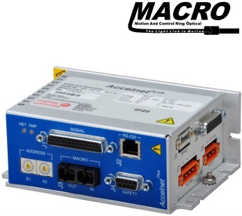
Accelnet Plus Panel MACRO BML
Control Modes
• Indexer, Point-to-Point, PVT
• Camming, Gearing
• Position, Velocity, Torque Command Interface
• MACRO
• ASCII and discrete I/O
• Stepper commands
• ±10V position/velocity/torque
• PWM velocity/torque command
• Master encoder (Gearing/Camming)
Communications
• MACRO
• RS-232
Feedback Incremental Encoders
• Digital quad A/B
Analog Sin/Cos
Panasonic Incremental A Format
Sanyo Denki Wire-Saving Incremental
• Aux. quad A/B encoder / encoder out
Absolute Encoders
• SSI, EnDat, BiSS (B & C)
Tamagawa, Panasonic, Sanyo Denki Absolute A
• Digital Halls
I/O Digital
• 6 High-speed inputs
• 1 Motor over-temp input
• 4 Opto-Isolated inputs
• 3 Opto-Isolated outputs
• 1 Opto-Isolated brake output
I/O Analog
• 1 Reference Input, 12-bit
Safe Torque Off (STO)
• SIL 3, Category 3, PL d
Dimensions: IN [mm]
• 5.08 x 3.41 x 1.99 [129 x 86.6 x 50.4]
• 5.08 x 3.41 x 3.39 [129 x 86.6 x 86.1] with heatsink
|
Model |
VDC |
IC |
IP |
|
BML-090-06 |
90 |
3 |
6 |
|
BML-090-14 |
90 |
7 |
14 |
|
BML-090-30 |
90 |
15 |
30 |
DESCRIPTION
The BML is a high-performance, DC powered drive for position, velocity,
and torque control of brushless and brush motors via MACRO.
Feedback from both incremental and absolute encoders is supported.
A multi-mode encoder port functions as an input or output depending on the drive’s basic setup.
There are seven non-isolated inputs. All inputs have programmable active levels.
Three opto-isolated outputs [OUT1~3] have individual +/- connections.
An isolated MOSFET brake output [OUT4] is programmable to drive motor brakes or
other functions and has a flyback diode to the Brake 24V input for driving inductive loads.
Drive power is transformer-isolated DC from regulated or unregulated power supplies.
An AuxHV input is provided for “keep-alive” operation permitting the drive power stage to be
completely powered down without losing position information, or communications with the control system.

Accelnet Micro Module High Current ACK
 Advanced Feature Set
• 32-bit floating point filters
• Multiple advanced filters
• CPL (Copley Programming Language)
• Frequency analysis tools
Control Modes
• Fast indexer, Point-to-Point, PVT, CSP
• Camming, Gearing, Position, Velocity, Torque
Command Interface
• CANopen
• ASCII, serial binary and discrete I/O
• Stepper commands
• ±10V position/velocity/torque command
• PWM velocity/torque command
• Master encoder (Gearing/Camming)
Communications
• CANopen
• RS-232 Feedback
• Digital Quad A/B encoder
• Secondary encoder
• Digital Halls
I/O - Digital
• 10 inputs, 3 outputs
Dimensions: mm [in]
• 63.5 x 40.6 x 21.1 [2.50 x 1.60 x 0.83]
|
Model |
VDC |
IC |
IP |
|
ACK-090-20 |
14-90 |
10 |
20 |
|
ACK-090-30 |
14-90 |
15 |
30 |
DESCRIPTION
Accelnet Micro Module with advanced feature set is a digital servodrive that combines
CANopen networking with 100% digital control of brush or brushless motors
in a PC board mounting package with power options to 15 Adc continuous and
30 Adc peak from 14 to 90 Vdc power supplies.
Accelnet Micro Module operates as a Motion Control Device using the CiA 402 protocol under the
CANopen DS-301 V4.01 (EN 50325- 4) application layer.
CiA 402 modes supported include Interpolated Position (PVT), Profile Position, Profile Velocity, Profile Torque,
and Homing. There are ten logic inputs. One is dedicated to the Amp Enable function, the other nine are programmable.
There are three logic outputs rated to +30 Vdc. Used as a stand-alone drive,
Accelnet Micro Module can operate using incremental position commands from step-motor controllers
in Pulse/ Direction or CU/CD format, as well as A/B quadrature commands from a master-encoder.Torque or
velocity control can be from digital PWM signals, or analog ±10 V.
Drive commissioning is facilitated by CME™ software operating under Windows® communicating with
Accelnet Micro Module via CAN or an RS-232 link.
Auto-tuning algorithms in CME™ slash set up times for fast system commissioning by automating motor phasing,
and current-loop tuning. A powerful oscilloscope and waveform generator displays drive performance for fine tuning.
Drive configurations are saved in non-volatile flash memory.
Space-vector modulation delivers higher motor speeds and lower motor power dissipation than conventional sine-PWM modulation.
Current-loop sampling is at 15 kHz, position and velocity loops at 3 kHz and PWM ripple at 30 kHz.
All drive circuits are DC coupled and operate from unregulated transformer-isolated linear DC power supplies,
or regulated switching power supplies. The PC-board mounting package is suitable for high-density,
multi-axis installations in equipment where space is at a premium, and wiring must be minimized.
資料來源: https://www.copleycontrols.com/wp-content/uploads/2018/07/ACK-HC-ds-2.pdf

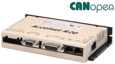
Accelnet R20
AFS Advanced Feature Set
• BiSS-C Unidirectional encoder, SSI (Consult factory)
• 32-bit floating point filters
• Multiple advanced filters
• Frequency analysis tools
CONTROL MODES
• Indexer, Point-to-Point, PVT
• Camming, Gearing, Position, Velocity, Torque
COMMAND INTERFACE
• Stepper commands
Single-ended or Differential selectable
• CANopen
• ASCII and discrete I/O
• ±10V position/velocity/torque command
• PWM position/velocity/torque command
• Master encoder (Gearing/Camming)
COMMUNICATIONS
• CANopen
• RS-232
• RS-422 (Optional)
FEEDBACK
• Digital quad A/B encoder
• Aux encoder / emulated encoder out
• Analog Sin/Cos encoder (-S versions)
• Digital Halls
I/O - DIGITAL
• 12 inputs, 3 outputs
DIMENSIONS: mm [in]
• 168 x 99 x 31 [6.6 x 3.9 x 1.2]
|
Model |
VDC |
IC |
IP |
|
R20-055-18 |
55 |
6 |
18 |
|
R20-090-09 |
90 |
3 |
9 |
|
R20-090-18 |
90 |
6 |
18 |
|
R20-090-36 |
90 |
12 |
36 |
|
R20-180-09 |
180 |
3 |
9 |
|
R20-180-18 |
180 |
6 |
18 |
|
R20-180-30 |
180 |
15 |
30 |
Add -S to part numbers above for Sin/Cos feedback
DESCRIPTION
REV 01 below the model number on the label indicates
Accelnet R20 with the advanced feature set.
R20 is a ruggedized highperformance, DC powered drive for position,
velocity (using encoder, Halls, or BEMF), and torque control of brushless and brush motors.
It operates as a distributed drive using the CANopen protocol, or as a stand-alone drive
accepting analog or digital commands from an external motion controller.
In stand-alone mode, current and velocity modes accept digital 50% PWM or PWM/polarity
inputs as well as ±10V analog. In position mode inputs can be incremental position commands
from step-motor controllers, analog ±10V, or A/B quadrature commands from a master-encoder.
Pulse to position ratio is programmable for electronic gearing. Accelnet R20 models operate as
Motion Control Devices under the DSP-402 protocol of the CANopen DS-301 V4.01 (EN 50325-4) application layer
DSP-402 modes supported include: Profile Position, Profile Velocity, Profile Torque, Interpolated Position Mode (PVT),
and Homing. The two CAN ports are optically isolated from drive circuits.
There are twelve digital inputs eleven of which have programmable functions.
These include CAN address, motion-abort, limit & home switches, stepper/encoder pulse inputs, reset,
digital torque or velocity reference, and motor over-temperature. Input [IN1] is dedicated for the drive Enable.
There are three programmable logic outputs for reporting an drive fault, motor brake control, or other status indications.
Drive power is transformer-isolated DC from regulated or unregulated power supplies.
An AuxHV input powers control circuits for “keep-alive” operation permitting the drive power stage to be completely
powered down without losing position information, or communications with the control system.
RUGGEDIZED STANDARDS CONFORMANCE
Ambient Temperature Non-Operating -50ºC to 85ºC
Operating -40ºC to 70ºC
Thermal Shock Operating -40ºC to 70ºC in 1 minute
Relative Humidity Non-Operating 95% non-condensing at 60ºC
Operating 95% non-condensing at 60ºC
Vibration Operating 5 Hz to 500 Hz, up to 3.85 grms
Altitude Non-Operating -400 m to 12,200 m
Operating -400 m to 5,000 m
Shock Crash Safety 75 g peak acceleration
Operating 40 g peak acceleration
MIL-STD specifications MIL-STD- 461, 704, 810, 1275, 1399
IEC specifications IEC- 60068, 60079
資料來源: https://www.copleycontrols.com/wp-content/uploads/2018/09/R20-REV01-ds.pdf

Accelnet R21
CONTROL MODES
• Indexer, Point-to-Point, PVT
• Camming, Gearing, Position, Velocity, Torque
COMMAND INTERFACE
• CANopen
• ASCII and discrete I/O
• Stepper commands
• ±10V position/velocity/torque command
• PWM position*/velocity/torque command
• Master encoder (Gearing/Camming)
COMMUNICATIONS
• CANopen
• RS-232
FEEDBACK
• Digital quad A/B encoder
• Aux encoder / emulated encoder out
• Analog sin/cos encoder (-S versions)
• Brushless resolver (-R versions)
• Digital Halls
I/O - DIGITAL
• 9 inputs, 4 outputs
DIMENSIONS: mm [in]
• 97 x 64 x 33 [3.8 x 2.5 x 1.3]
* R21-R models
|
Model |
VDC |
IC |
IP |
|
R21-055-09 |
20-55 |
3 |
9 |
|
R21-055-18 |
20-55 |
6 |
18 |
|
R21-090-03 |
20-90 |
1 |
3 |
|
R21-090-09 |
20-90 |
3 |
9 |
|
R21-090-12 |
20-90 |
6 |
12 |
* Note: Add “-S” to part number for Sin/Cos version
Add “-R” to part number for resolver version
DESCRIPTION
Accelnet R21 is a compact, DC powered servo drive for position,
velocity, and torque control of AC brushless and DC brush motors.
It can operate on a distributed control network, as a stand-alone indexing drive,
or with external motion controllers.
Two versions are available to support digital quadrature, or analog sin/cos encoders.
Indexing mode enables simplified operation with PLC’s which use outputs to select
and launch indexes and inputs to read back drive status. Additionally,
a PLC can send ASCII data that can change motion profiles so that one index can
perform various motions as machine requirements change.
The CANopen distributed control architecture is also supported.
As a CAN node operating under the CANopen protocol, it supports Profile Position,
Profile Velocity, Profile Torque, Interpolated Position, and Homing.
Up to 127 drives can operate on a single CAN bus and groups of drives can be
linked via the CAN so that they execute motion profiles together.
Operation with external motion controllers is possible in torque (current), velocity,
and position modes. Input command signals can be ±10V (torque, velocity, position),
PWM/Polarity (torque, velocity), or stepper format (CU/CD or Step/Direction).
RUGGEDIZED STANDARDS CONFORMANCE
Ambient Temperature Non-Operating -50ºC to 85ºC
Operating -40ºC to 70ºC
Thermal Shock Operating -40ºC to 70ºC in 1 minute
Relative Humidity Non-Operating 95% non-condensing at 60ºC
Operating 95% non-condensing at 60ºC
Vibration Operating 5 Hz to 500 Hz, up to 3.85 grms
Altitude Non-Operating -400 m to 12,200 m
Operating -400 m to 5,000 m
Shock Crash Safety 75 g peak acceleration
Operating 40 g peak acceleration
MIL-STD specifications MIL-STD- 461, 704, 810, 1275, 1399
IEC specifications IEC- 60068, 60079

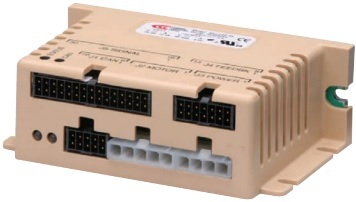
Accelnet R22
Control Modes
• Indexer, Point-to-Point, PVT
• Camming, Gearing, Position, Velocity, Torque
Command Interface
• CANopen
• ASCII and discrete I/O
• Stepper commands
• PWM velocity/torque command
• Master encoder (Gearing/Camming)
• ±10 Vdc analog position/velocity/torque
Communications
• CANopen
• RS-232 Feedback
• Digital quad A/B encoder
• Secondary encoder
• Brushless resolver (-R option)
• Digital Halls
I/O - Digital
• 10 inputs, 2 outputs
Dimensions: mm [in]
• 102 x 69 x 25 [4.0 x 2.7 x 1.0]
|
Model |
VDC |
IC |
IP |
|
R22-055-18 |
20-55 |
6 |
18 |
|
R22-090-09 |
20-90 |
3 |
9 |
|
R22-090-24 |
20-90 |
12 |
24 |
|
R22-090-60 |
20-90 |
30 |
60 |
|
R22-180-09 |
20-180 |
3 |
9 |
|
R22-180-18 |
20-180 |
6 |
18 |
|
R22-180-20 |
20-180 |
10 |
20 |
Add -R to part number for resolver option
DESCRIPTION
Accelnet R22 is a ruggedized, PC board-mounting digital servo drive that combines
CANopen networking with 100% digital control of brush or brushless motors.
It operates as a Motion Control Device using the DSP-402 protocol under the
CANopen DS-301 V4.01 (EN 50325-4) application layer. DSP-402 modes supported
include Interpolated Position (PVT), Profile Position, Profile Velocity, Profile Torque,
and Homing.
A ±10 Vdc analog input has been added for position/velocity/torque control.
Ten logic inputs are configurable as CAN address bits, enables, limit & home switches,
motor temperature switch, stepper/encoder pulses, and reset. Two logic outputs are
programmable to report drive status, or to drive a motor brake.
As a stand-alone drive Accelnet R22 can operate using incremental position commands
from step-motor controllers in Pls/Dir or CW/CCW format, as well as A/B quadrature
commands from a master-encoder.Drive commissioning is facilitated by CME 2™ software
operating under Windows® communicating with Accelnet R22 via an RS-232 link.
Auto-tuning algorithms in CME 2™ slash set up times for fast system commissioning by
automating motor phasing, and current-loop tuning.
A powerful oscilloscope and waveform generator display drive performance for fine tuning.
Drive configurations are saved in non-volatile flash memory.
OEM’s can inventory one part, and configure drives on-site to each axis in a machine.
All drive circuits are DC coupled and operate from unregulated transformer-isolated
linear DC power supplies, or regulated switching power supplies.
The pc-board mounting package is suitable for high-density, multi-axis installations in
equipment where space is at a premium, and wiring must be minimized.
RUGGEDIZED STANDARDS CONFORMANCE
Ambient Temperature Non-Operating -50ºC to 85ºC
Operating -40ºC to 70ºC
Thermal Shock Operating -40ºC to 70ºC in 1 minute
Relative Humidity Non-Operating 95% non-condensing at 60ºC
Operating 95% non-condensing at 60ºC
Vibration Operating 5 Hz to 500 Hz, up to 3.85 grms
Altitude Non-Operating -400 m to 12,200 m
Operating -400 m to 5,000 m
Shock Crash Safety 75 g peak acceleration
Operating 40 g peak acceleration
MIL-STD specifications MIL-STD- 461, 704, 810, 1275, 1399
IEC specifications IEC- 60068, 60079

Accelnet R23
Control Modes
• Indexer, Point-to-Point, PVT
• Camming, Gearing, Position, Velocity, Torque
Command Interface
• CANopen
• ASCII and discrete I/O
• Stepper commands
• ±10V position/velocity/torque command
• PWM velocity/torque command
• Master encoder (Gearing/Camming)
Communications
• CANopen
• RS232 Feedback
• Digital Quad A/B encoder
• Secondary encoder
• Digital Halls
• Resolver (-R option)
I/O - Digital
• 10 inputs, 3 outputs
Dimensions: mm [in]
• 64 x 41 x 16 [2.5 x 1.6 x 0.6]
|
Model |
VDC |
IC |
IP |
|
R23-055-06 |
14-55 |
3 |
6 |
|
R23-055-10 |
20-55 |
5 |
10 |
|
R23-090-04 |
14-90 |
2 |
4 |
|
R23-090-08 |
20-90 |
4 |
8 |
For resolver option, add “-R” to the part numbe
DESCRIPTION
Accelnet R23 is a digital servodrive that combines CANopen networking with 100% digital
control of brush or brushless motors in a pc board mounting package.
Accelnet R23 operates as a Motion Control Device using the DSP-402 protocol under the
CANopen DS-301 V4.01 (EN 50325-4) application layer.
DSP-402 modes supported include Interpolated Position (PVT), Profile Position, Profile Velocity,
Profile Torque, and Homing. There are ten logic inputs.
One is dedicated to the Amp Enable function, the other nine are programmable.
There are three logic outputs rated to +30 Vdc. Used as a stand-alone drive, Accelnet R23 can
operate using incremental position commands from step-motor controllers in
Pulse/Direction or CU/CD format, as well as A/B quadrature commands from a masterencoder.
Torque or velocity control can be from digital PWM signals, or analog ±10 V.
Drive commissioning is facilitated by CME 2™ software operating under Windows® communicating
with Accelnet R23 via CAN or an RS-232 link.
Auto-tuning algorithms in CME 2™ slash set up times for fast system commissioning by automating
motor phasing, and current-loop tuning.
A powerful oscilloscope and waveform generator displays drive performance for fine tuning.
Drive configurations are saved in non-volatile flash memory. OEM’s can inventory one part,
and configure drives onsite to each axis in a machine.
Space-vector modulation delivers higher motor speeds and lower motor power dissipation than
conventional sine-pwm modulation.
Carriercancellation modulation all but eliminates motor ripple current and dissipation at a standstill.
Current-loop sampling is at 15 kHz, position and velocity loops at 3 kHz and PWM ripple at 30 kHz.
All drive circuits are DC coupled and operate from unregulated transformer-isolated linear DC power supplies,
or regulated switching power supplies. The pc-board mounting package is suitable for high-density,
multi-axis installations in equipment where space is at a premium, and wiring must be minimized.
RUGGEDIZED STANDARDS CONFORMANCE
Ambient Temperature Non-Operating -50ºC to 85ºC
Operating -40ºC to 70ºC
Thermal Shock Operating -40ºC to 70ºC in 1 minute
Relative Humidity Non-Operating 95% non-condensing at 60ºC
Operating 95% non-condensing at 60ºC
Vibration Operating 5 Hz to 500 Hz, up to 3.85 grms
Altitude Non-Operating -400 m to 12,200 m
Operating -400 m to 5,000 m
Shock Crash Safety 75 g peak acceleration
Operating 40 g peak acceleration
MIL-STD specifications MIL-STD- 461, 704, 810, 1275, 1399
IEC specifications IEC- 60068, 60079

Accelnet Plus R42
Control Modes
• Position, Velocity, Torque
• Indexer, Point-to-Point, PVT
• Camming, Gearing
Command Interface
• CANopen
• ASCII and discrete I/O
• Stepper commands
• ±10V position/velocity/torque command
• PWM velocity/torque command
• Master encoder (Gearing/Camming)
Communications
• CANopen
• RS-232
Feedback
• Incremental
• Digital quad A/B encoder
• Analog sin/cos encoder
• Panasonic Incremental A
• Digital Halls Absolute
• SSI
• EnDat
• Absolute A
• Tamagawa Absolute A
• Panasonic Absolute A Format
• BiSS (B & C)
I/O
• Digital: 11 inputs, 6 outputs
• Analog: 1 input
Dimensions: mm [in]
• 76.3 x 58.2 x 20.5 [3.01 x 2.29 x 0.81]
|
Model |
IC |
IP |
|
R42-090-06 |
3 |
6 |
|
R42-090-14 |
7 |
14 |
|
R42-090-30 |
15 |
30 |
DESCRIPTION
Accelnet R42 is a high-performance, ruggedized, DC powered servo drive for position,
velocity, and torque control of brushless and brush motors via CANopen.
Using advanced FPGA technology, the R42 provides a significant reduction in the cost
per node in multi-axis CANopen systems. The R42 operates as an CANopen node using
the CANopen over CANopen (CoE) protocol of DSP-402 for motion control devices.
Supported modes include: Profile Position-Velocity-Torque, Interpolated Position Mode (PVT),
and Homing. Command sources also include ±10V analog torque/velocity/position,
PWM torque/velocity, and stepper command pulses.
Feedback from a number of incremental and absolute encoders is supported.
Nine high-speed digital inputs with programmable functions are provided,
and a low-speed input for motor temperature switches.
An SLI (Switch & LED Interface) function is supported by another high-speed input and
four high-speed digital outputs. If not used for SLI, the input and outputs are programmable
for other functions. Two open-drain MOSFET outputs can drive loads powered up to 24 Vdc.
An RS-232 serial port provides a connection to Copley’s CME2 software for commissioning,
firmware upgrading, and saving configurations to flash memory.
Drive power is transformer-isolated DC from regulated or unregulated power supplies.
An AuxHV input is provided for “keep-alive” operation permitting the drive power stage to be
completely powered down without losing position information, or communications with the control system.
RUGGEDIZED STANDARDS CONFORMANCE
Ambient Temperature Non-Operating -50ºC to 85ºC
Operating -40ºC to 70ºC
Thermal Shock Operating -40ºC to 70ºC in 1 minute
Relative Humidity Non-Operating 95% non-condensing at 60ºC
Operating 95% non-condensing at 60ºC
Vibration Operating 5 Hz to 500 Hz, up to 3.85 grms
Altitude Non-Operating -400 m to 16,000 m
Operating -400 m to 16,000 m
Shock Crash Safety 75 g peak acceleration
Operating 40 g peak acceleration
MIL-STD specifications MIL-STD- 461, 704, 810, 1275, 1399
IEC specifications IEC- 60068, 60079
資料來源: https://www.copleycontrols.com/wp-content/uploads/2018/02/R42_DS.pdf

Control Modes
• Profile Position-Velocity-Torque, Interpolated Position (PT,PVT), Homing
• Indexer, Point-to-Point, CPL
• Camming, Gearing
• Position, Velocity, Torque
Command Interface
• CANopen
• ASCII, Serial Binary, and discrete I/O
• Stepper or Quad A/B position commands
• PWM Velocity/Torque command
• Master encoder (Gearing/Camming)
Communications
• CANopen
• RS-232
Feedback
• Dual Absolute Encoder Ports
SSI
EnDat 2.1, 2.2
Absolute A
Tamagawa Absolute A
Panasonic , Sanyo Denki Absolute A Format
BiSS
• Incremental
Digital quad A/B/X encoder
Analog Sin/Cos encoder
• Other
Digital Halls
I/O
• 7 High-speed digital inputs
• 6 High-speed digital outputs
• 1 Differential analog input
Safe Torque Off (STO)
• SIL 3, Category 3, PL e
Dimensions: in [mm]
• 2.5 x 1.6 x .69 [64 x 41 x 17.6]
|
Model |
IC |
IP |
VDC |
|
R43-090-14 |
7 |
14 |
9~90 |
|
R43-090-30 |
15 |
30 |
9~90 |
|
R43-090-50 |
25 |
50 |
9~90 |
|
R43-090-50-C |
50 |
50 |
9~90 |
|
R43-180-10 |
5 |
10 |
20~180 |
|
R43-180-20 |
10 |
20 |
20~180 |
DESCRIPTION
R43 sets new levels of performance, connectivity, and flexibility.
CANopen communication provides a widely used cost-effective
industrial bus. A wide range of absolute encoders are supported.
Safe Torque Off (STO) eliminates external contactors and wiring,
reducing system cost and complexity. For safety critical applications,
redundant STO disable inputs can be employed.
RUGGEDIZED STANDARDS CONFORMANCE
Ambient Temperature Non-Operating -50ºC to 85ºC
Operating -40ºC to 70ºC
Thermal Shock Operating -40ºC to 70ºC in 1 minute
Relative Humidity Non-Operating 95% non-condensing at 60ºC
Operating 95% non-condensing at 60ºC
Vibration Operating 5 Hz to 500 Hz, up to 3.85 grms
Altitude Non-Operating -400 m to 16,000 m
Operating -400 m to 16,000 m
Shock Crash Safety 75 g peak acceleration
Operating 40 g peak acceleration
MIL-STD specifications MIL-STD- 461, 704, 810, 1275, 1399
IEC specifications IEC- 60068, 60079
原廠網址: https://www.copleycontrols.com/wp-content/uploads/2020/05/R43-ds.pdf

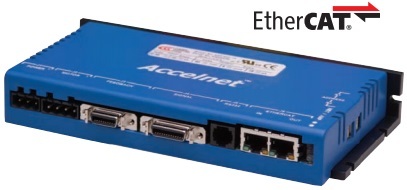
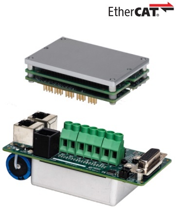
Accelnet Plus Panel EtherCAT AEP
Control Modes
• Indexer, Point-to-Point, PVT
• Camming, Gearing
• Position, Velocity, Torque
Command Interface
• CAN application layer over EtherCAT (CoE)
• ±10V position/velocity/torque
• Master encoder (Gearing/Camming)
• ASCII via RS-232 Communications
• EtherCAT CoE (CAN application layer over EtherCAT)
• RS-232
Feedback Incremental
• Digital quad A/B encoder
• Analog sin/cos encoder
• Panasonic Incremental A
• Digital Halls
• Aux. encoder / encoder out Absolute
• SSI
• EnDat
• Absolute A
• Tamagawa Absolute A
• Panasonic Absolute A Format
• BiSS (B&C)
I/O Digital
• 8 inputs, 3 outputs
Dimensions: mm [in]
• 196 x 99 x 31 [7.7 x 3.9 x 1.2]
|
Model |
VDC |
IC |
IP |
|
AEP-055-18 |
55 |
6 |
18 |
|
AEP-090-09 |
90 |
3 |
9 |
|
AEP-090-18 |
90 |
6 |
18 |
|
AEP-090-36 |
90 |
12 |
36 |
|
AEP-180-09 |
180 |
3 |
9 |
|
AEP-180-18 |
180 |
6 |
18 |
DESCRIPTION
Accelnet EtherCAT is a high-performance, DC powered drive for position, velocity,
and torque control of brushless and brush motors via EtherCAT, an Ethernet-based fieldbus.
Drive commissioning is fast and simple using CME 2™ software operating under Windows®
and communicating with Accelnet EtherCAT via RS-232. Accelnet operates as an EtherCAT slave
using the CAN application layer over EtherCAT (CoE) protocol of DSP-402 for motion control devices.
Supported modes include: Profile Position-Velocity-Torque, Cyclic Synchronous Position-Velocity-Torque,
Interpolated Position Mode (PVT), and Homing. Feedback from both incremental and absolute encoders
is supported. A multi-mode encoder port functions as an input or output depending on the drive’s basic setup.
As a input it takes feedback from a secondary encoder to create a dual-loop position control system or as a
master encoder for driving a cam table. As an output, it buffers the digital encoder signals from the motor’s
digital encoder and eliminate split cables that would be needed to send the signals to both drive and
control system.
There are six opto-isolated digital inputs in two groups. All are common-anode types that source current into
current-sinking switches in the controller. Inputs [IN1~4] are 24 Vdc compatible and inputs [IN5~6] are 5 Vdc
compatible.
The active levels are programmable as are the functions. The drive Enable function is dedicated to [IN1].
A non-isolated high-speed input [IN7] and output [OUT3] are provided, as well as two opto-isolated Darlington
outputs [OUT1,2].
In addition, a ±10 Vdc analog input is provided for interfacing to sensors. Drive power is transformer-isolated
DC from regulated or unregulated power supplies. An AuxHV input is provided for “keep-alive” operation
permitting the drivepower stage to be completely powered down without losing position information,
or communications with the control system.

Accelnet Plus Micro Module EtherCAT AEV
Control Modes
• Cyclic Synchronous Position-Velocity-Torque (CSP, CSV, CST)
• Cyclic Synchronous Torque with Commutation Angle (CSTCA)
• Profile Position-Velocity-Torque, Interpolated Position (PT,PVT), Homing
• Indexer, Point-to-Point, CPL
• Camming, Gearing
• Position, Velocity, Torque
Command Interface
• CANopen application protocol over EtherCAT (CoE)
• ASCII, Serial Binary, and discrete I/O
• Stepper or Quad A/B position commands
• PWM velocity/torque command
• Master encoder (Gearing/Camming)
Communications
• EtherCAT
• RS-232
Feedback
• Dual Absolute Encoder Ports
SSI
EnDat 2.1, 2.2
Absolute A
Tamagawa Absolute A
Panasonic , Sanyo Denki Absolute A Format
BiSS
• Incremental
Digital quad A/B/X encoder
Analog Sin/Cos encoder
• Other
Digital Halls
I/O
• 7 High-speed digital inputs
• 6 High-speed digital outputs
• 1 Differential analog input
Safe Torque Off (STO)
• SIL 3, Category 3, PL d
Dimensions: mm [in]
• 64 x 41 x 16.5 [2.5 x 1.6 x .65] AEV
• 112 x 53.3 x 42.4 [4.4 x 2.1 x 1.7] AEZ
|
Model |
VDC |
IC |
IP |
|
AEV-090-14 |
9-90 |
7 |
14 |
|
AEV-090-30 |
9-90 |
15 |
30 |
|
AEV-090-50 |
9-90 |
25 |
50 |
|
AEZ-090-50 |
9-90 |
25 |
50 |
|
AEV-180-10 |
20-180 |
5 |
10 |
|
AEV-180-20 |
20-180 |
10 |
20 |
DESCRIPTION
AEV sets new levels of performance, connectivity, and
flexibility. CANopen application protocol over EtherCAT (CoE)
communication provides a widely used cost-effective industrial
bus. A wide range of absolute encoders are supported.
Safe Torque Off (STO) eliminates external contactors and
wiring, reducing system cost and complexity. For safety critical
applications, redundant STO disable inputs can be employed.
資料來源: https://www.copleycontrols.com/wp-content/uploads/2019/02/AEV-ds-1.pdf

Accelnet Plus Micro Module CANopen APV
Control Modes
• Profile Position-Velocity-Torque, Interpolated Position (PT,PVT), Homing
• Indexer, Point-to-Point, CPL
• Camming, Gearing
• Position, Velocity, Torque
Command Interface
• CANopen
• ASCII, Serial Binary, and discrete I/O
• Stepper or Quad A/B position commands
• PWM velocity/torque command
• Master encoder (Gearing/Camming)
Communications
• CANopen
• RS-232
Feedback
• Dual Absolute Encoder Ports
SSI
EnDat 2.1, 2.2
Absolute A
Tamagawa Absolute A
Panasonic , Sanyo Denki Absolute A Format
BiSS
• Incremental
Digital quad A/B/X encoder
Analog Sin/Cos encoder
• Other
Digital Halls
I/O
• 7 High-speed digital inputs
• 6 High-speed digital outputs
• 1 Differential analog input
Safe Torque Off (STO)
• SIL 3, Category 3, PL d
Dimensions: mm [in]
• 64 x 41 x 16.5 [2.5 x 1.6 x .65] APV
• 112 x 53.3 x 42.4 [4.4 x 2.1 x 1.7] APZ
|
Model |
VDC |
IC |
IP |
|
APV-090-14 |
9-90 |
7 |
14 |
|
APV-090-30 |
9-90 |
15 |
30 |
|
APV-090-50 |
9-90 |
25 |
50 |
|
APZ-090-50 |
9-90 |
25 |
50 |
|
APV-180-10 |
20-180 |
5 |
10 |
|
APV-180-20 |
20-180 |
10 |
20 |
DESCRIPTION
APV sets new levels of performance, connectivity, and flexibility.
CANopen communication provides a widely used cost-effective
industrial bus. A wide range of absolute encoders are supported.
Safe Torque Off (STO) eliminates external contactors and wiring,
reducing system cost and complexity. For safety critical applications,
redundant STO disable inputs can be employed.
資料來源: https://www.copleycontrols.com/wp-content/uploads/2019/02/APV-ds.pdf